Title here
Summary here
At Ph0wn 2026, a CTF conference focused on hardware and embedded security, Cyril Marpaud ran a hands-on workshop on writing embedded Rust for the BBC micro:bit. The lab materials are publicly available on his GitLab: gitlab.com/cyril-marpaud/ph0wn.
I used Rust about three years ago and have been fairly rusty since. This workshop was a good excuse to get back up to speed through a concrete hardware goal: display a heart on the micro:bit’s LED matrix, entirely in Rust, at register level.
This article documents the setup and the steps taken to get there.
The micro:bit is a small single-board computer designed in the UK, originally for teaching programming to school children. It is now available to the general public in many countries and has become popular in the maker and embedded communities.
Despite its educational origins, the hardware is genuinely capable: the v2 board runs an ARM Cortex-M4 (Nordic nRF52833) with Bluetooth, a built-in sensor suite, and an onboard USB debugger. No external probe is needed to flash or debug code.
nRF is the microcontroller family from Nordic Semiconductor. The nRF52833 is the specific chip used on the micro:bit v2.
Traditional embedded development is done in C. Rust offers the same level of control over the hardware with a key advantage: the compiler catches entire classes of bugs at compile time (null pointer dereferences, buffer overflows, data races) without any runtime cost.
For embedded systems this matters a lot: there is no OS to catch crashes, no memory allocator to absorb misuse, and bugs can be silent or destructive. Rust’s ownership model makes unsafe memory access a compile error rather than a runtime surprise.
The embedded Rust ecosystem covers the full stack.
embedded-hal defines hardware abstraction traits (SPI, I2C, UART) that driver crates implement, making drivers portable across chips.
nrf52833-pac is the Peripheral Access Crate (PAC) for the nRF52833, generated from Nordic’s SVD file. It gives direct register-level access and sits one level below a full HAL, which would add a higher-level API on top.
probe-rs handles flashing and debugging over SWD via the onboard DAPLink.
The goal of this section is to get a minimal Rust project that compiles and runs on the micro:bit. No peripherals yet, just proof that the toolchain works end to end.
rustup-init -yThis installs rustup, rustc, and cargo with default settings. Reload your shell afterwards (source ~/.cargo/env) or open a new terminal.
cargo new microbit --bin
cd microbitThe nRF52833 is a Cortex-M4 with a hardware FPU. Rust needs the matching cross-compilation target:
rustup target add thumbv7em-none-eabihfThe .cargo/config.toml file sets the default build target for the project so Cargo knows which toolchain to use without specifying it on every command. It also tells Cargo to use probe-rs as the runner, which means cargo run will compile, flash the board, and start execution automatically.
.cargo/config.toml:
[build]
target = "thumbv7em-none-eabihf"

[target.thumbv7em-none-eabihf]
runner = "probe-rs run --chip nRF52833_xxAA"The workshop works at the PAC level (Peripheral Access Crate) rather than a higher-level board support crate. The PAC gives direct access to the hardware registers, which is closer to how embedded C code works and makes it easier to understand what is actually happening on the chip.
[dependencies]
nrf52833-pac = "0.12"
cortex-m-rt = "0.7"
cortex-m = { version = "0.7", features = ["critical-section-single-core"] }
cortex-m-rt provides the runtime for Cortex-M targets (reset handler, interrupt table). cortex-m is the low-level access crate for Cortex-M peripherals. The critical-section-single-core feature provides a critical section implementation: a region of code that cannot be interrupted, implemented here by temporarily disabling interrupts. It is required at link time by the PAC and by the logging crates added later. Without it, the build fails with a missing symbol error.
cortex-m-rt requires two files to link the firmware correctly.
memory.x tells the linker where flash and RAM are on the nRF52833:
MEMORY
{
  FLASH : ORIGIN = 0x00000000, LENGTH = 512K
  RAM   : ORIGIN = 0x20000000, LENGTH = 128K
}
build.rs is a Rust build script that Cargo runs before compilation. It copies memory.x to the build output directory and tells Cargo to pass the link.x linker script (provided by cortex-m-rt) to the linker:
println!("cargo:rustc-link-arg=-Tlink.x");Without link.x, the linker does not know how to lay out the interrupt vector table, stack, and code sections for Cortex-M. Without memory.x, it does not know the chip’s memory map.
Both files are available from the nrf-hal repository:
wget https://raw.githubusercontent.com/nrf-rs/nrf-hal/refs/heads/master/nrf52833-hal/build.rs
wget https://raw.githubusercontent.com/nrf-rs/nrf-hal/refs/heads/master/nrf52833-hal/memory.x
If you are targeting a different nRF chip, pick the matching folder from nrf-rs/nrf-hal.
The project layout is now:
microbit/
├── .cargo/
│   └── config.toml
├── src/
│   └── main.rs
├── build.rs
├── memory.x
└── Cargo.tomlWriting a bare-metal Rust program is different from a standard Rust binary. On a PC, the OS sets up the stack, calls main, and handles panics. On a microcontroller, none of that exists. Everything must be declared explicitly.
#![no_std] disables the standard library, which assumes an OS underneath. Only core remains, the OS-independent subset of the Rust standard library. #![no_main] tells the compiler we will not provide a conventional main symbol. Instead, the #[entry] macro from cortex-m-rt defines the reset handler the CPU jumps to on boot and registers all the default interrupt handlers the linker expects (including DefaultHandler_). Without it, the build fails with symbol not found: DefaultHandler_. The entry function must return ! because there is nothing to return to.
Without std, there is also no default panic behavior. The compiler requires a #[panic_handler] function. For now, an infinite loop is enough.
// src/main.rs
#![no_std]
#![no_main]

use cortex_m_rt::entry;
use core::panic::PanicInfo;

#[entry]
fn main() -> ! {
    loop {}
}

#[panic_handler]
fn panic(_info: &PanicInfo) -> ! {
    loop {}
}
Build and flash with:
cargo runThe board boots and loops silently. No output is expected at this stage. If cargo run completes without error, the full toolchain is working correctly.
On bare metal there is no stdout or terminal. To get output from the board, the standard approach is RTT (Real-Time Transfer), a protocol that streams data over the SWD debug connection already used by probe-rs. No extra wiring is needed.
Add the required crates:
cargo add defmt rtt-target
cargo add panic-probe --features print-rtt
rtt-target handles the low-level RTT transport. defmt is a deferred-formatting framework: it moves string formatting work to the host instead of the microcontroller, keeping the firmware small. panic-probe replaces the manual #[panic_handler] loop: it sends the panic message over RTT before halting, so instead of a silent freeze you get the exact panic location in the terminal.
Update main.rs:
use cortex_m as _;
use cortex_m_rt::entry;
use panic_probe as _;

#[entry]
fn main() -> ! {
    rtt_target::rtt_init_print!();
    rtt_target::rprintln!("Hello, World!");
    loop {}
}
use cortex_m as _ pulls in the critical-section implementation without importing any names. use panic_probe as _ registers the RTT panic handler. The as _ syntax imports only the side effects of the crate without polluting the namespace.
rtt_init_print!() sets up the RTT channel once at startup. rprintln! works like println! but sends output over the debug connection. When you run cargo run, probe-rs reads the RTT stream and prints it in the terminal automatically.
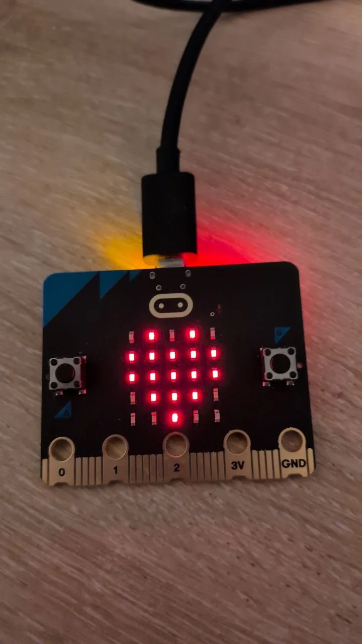
The goal is to display a heart on the 5x5 LED matrix. To get there, we first need to understand how the matrix is wired, then how to control GPIO at register level, then how multiplexing works.
The micro:bit v2 has a 5x5 LED matrix of 25 LEDs arranged in 5 rows and 5 columns. The LEDs are not wired individually to 25 GPIO pins. Instead the matrix is multiplexed: 5 row pins and 5 column pins control the whole grid.
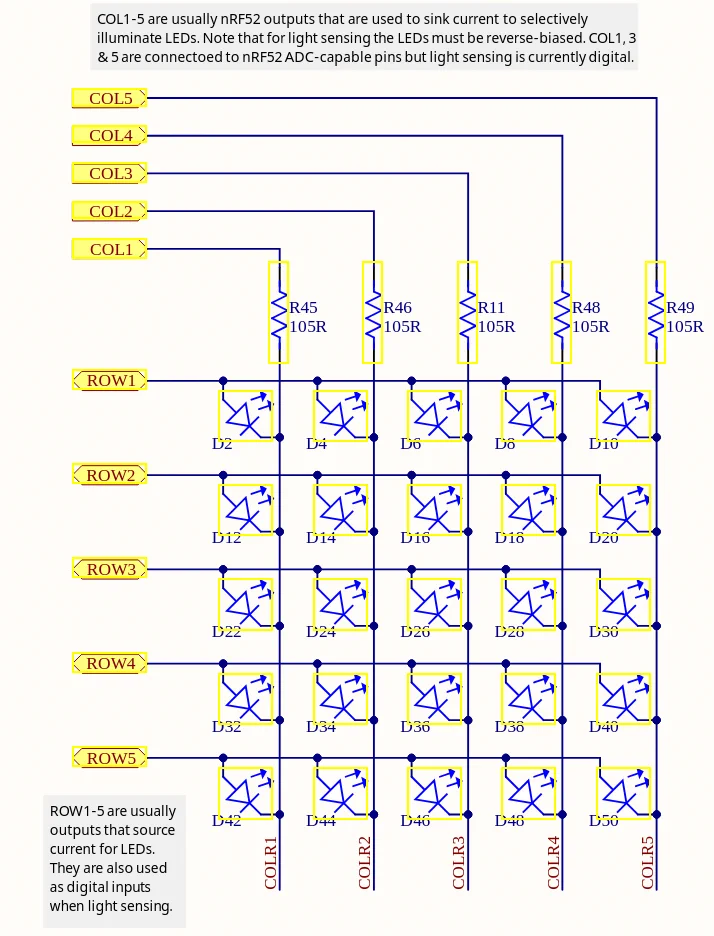
The anodes of the LEDs are connected to the row lines, and the cathodes to the column lines. A LED conducts current only when its anode is at a higher voltage than its cathode. Applying voltage in reverse blocks it. To light up a specific LED, its ROW pin must be set high (1) and its COL pin set low (0). Any other combination leaves the LED off.
The schematic (PDF) shows the matrix labelled ROWx and COLx. Cross-referencing with the PAC documentation gives the GPIO pin assignments:
| Signal | GPIO |
|---|---|
| ROW1 | P0.21 |
| ROW2 | P0.22 |
| ROW3 | P0.15 |
| ROW4 | P0.24 |
| ROW5 | P0.19 |
| COL1 | P0.28 |
| COL2 | P0.11 |
| COL3 | P0.31 |
| COL4 | P1.05 |
| COL5 | P0.30 |
Note that COL4 is on port P1 (a second GPIO port), while all other pins are on P0.
The PAC exposes the GPIO port through the P0 (and P1) peripheral. The
register block contains:
pub struct RegisterBlock {
    pub out: OUT,         // set output value for all pins at once
    pub outset: OUTSET,   // set pins high atomically (write 1 to set)
    pub outclr: OUTCLR,   // set pins low atomically (write 1 to clear)
    pub in_: IN,          // read input values
    pub dir: DIR,         // set direction for all pins at once
    pub dirset: DIRSET,   // set pins as output atomically
    pub dirclr: DIRCLR,   // set pins as input atomically
    pub pin_cnf: [PIN_CNF; 32], // per-pin configuration
    // ...
}
Before writing to a pin, it must be configured as an output through pin_cnf, otherwise the write has no effect. OUTSET and OUTCLR are preferred over OUT for toggling individual pins: they are atomic, so writing a 1 to a bit position affects only that pin without risking a race condition on the others.
The PAC exposes these registers via a closure-based API:
p.P0.pin_cnf[21].write(|w| w.dir().output()); // configure pin 21 as output
p.P0.outset.write(|w| unsafe { w.bits(1 << 21) }); // set pin 21 high
The write(|w| ...) pattern is specific to PAC-generated code. The closure receives a write proxy that only exposes valid fields for that register, making invalid writes a compile error.
Before tackling the full matrix, light up a single LED to confirm the wiring. Configure ROW1 (P0.21) and COL1 (P0.28) as outputs, then set ROW1 high. COL1 is left low by default, so the first LED lights up.
#![no_std]
#![no_main]

use cortex_m_rt::entry;
use cortex_m as _;
use panic_probe as _;
use nrf52833_pac::Peripherals;

#[entry]
fn main() -> ! {
    let p = Peripherals::take().unwrap();

    // Configure ROW1 and COL1 as outputs
    p.P0.pin_cnf[21].write(|w| w.dir().output()); // ROW1
    p.P0.pin_cnf[28].write(|w| w.dir().output()); // COL1

    // ROW1 high, COL1 stays low -> LED on
    p.P0.out.write(|w| w.pin21().high());

    loop {}
}
Peripherals::take() returns the singleton that owns all hardware peripherals. It can only be called once; a second call returns None. This is Rust’s way of enforcing at compile time that no two parts of the code can have mutable access to the same peripheral at the same time.
Now the objective is to display a heart. The heart pattern as a 25-element boolean array (row-major, top to bottom, left to right):
let heart = [
    false, true,  false, true,  false,  // . * . * .
    true,  true,  true,  true,  true,   // * * * * *
    true,  true,  true,  true,  true,   // * * * * *
    false, true,  true,  true,  false,  // . * * * .
    false, false, true,  false, false,  // . . * . .
];
A naive approach iterates all 25 cells and sets each row and column pin accordingly:
fn set_led_board(p: &Peripherals, tab: [bool; 25]) {
    let rows = [21, 22, 15, 24, 19];
    let cols = [28, 11, 31, 0, 30];

    for row in 0..5 {
        for col in 0..5 {
            let cell = tab[row * 5 + col];
            if cell {
                p.P0.outset.write(|w| unsafe { w.bits(1 << rows[row]) });
            } else {
                p.P0.outclr.write(|w| unsafe { w.bits(1 << rows[row]) });
            }
            if col == 3 {
                if cell { p.P1.outclr.write(|w| unsafe { w.bits(1 << 5) }); }
                else    { p.P1.outset.write(|w| unsafe { w.bits(1 << 5) }); }
            } else {
                if cell { p.P0.outclr.write(|w| unsafe { w.bits(1 << cols[col]) }); }
                else    { p.P0.outset.write(|w| unsafe { w.bits(1 << cols[col]) }); }
            }
        }
    }
}
This does not work correctly. The result on the board is not a heart:
* * * * *
* * * * *
* * | * *
* * | * *
* * * * *
The problem is that row and column pins are shared across the whole matrix. Each pin ends up in the state left by the last cell that touched it in the loop. A column set low for one LED gets overwritten to high when the next cell on that column is off. The final state is not the intended pattern.
To display a stable image on a multiplexed matrix, the trick is row scanning: activate one row at a time, configure the column pins for that row’s pixels, hold briefly, then move to the next row. Cycling through all 5 rows fast enough (above ~50 Hz) makes the human eye perceive a complete, stable image.
cortex_m::asm::delay(n) executes n CPU cycles of busy-wait. On the nRF52833 at 64 MHz, 10 000 cycles is about 156 µs per row, giving roughly 1280 full frames per second. Well above the persistence-of-vision threshold.
#![no_std]
#![no_main]

use cortex_m_rt::entry;
use cortex_m as _;
use panic_probe as _;
use nrf52833_pac::Peripherals;

fn init_leds(p: &Peripherals) {
    // row init
    p.P0.pin_cnf[21].write(|w| w.dir().output());
    p.P0.pin_cnf[22].write(|w| w.dir().output());
    p.P0.pin_cnf[15].write(|w| w.dir().output());
    p.P0.pin_cnf[24].write(|w| w.dir().output());
    p.P0.pin_cnf[19].write(|w| w.dir().output());

    // col init
    p.P0.pin_cnf[28].write(|w| w.dir().output());
    p.P0.pin_cnf[11].write(|w| w.dir().output());
    p.P0.pin_cnf[31].write(|w| w.dir().output());
    p.P1.pin_cnf[05].write(|w| w.dir().output());
    p.P0.pin_cnf[30].write(|w| w.dir().output());
}

fn set_led_board(p: &Peripherals, tab: [bool; 25]) {
    let rows = [21u32, 22, 15, 24, 19];
    let cols = [28u32, 11, 31, 0, 30]; // index 3 (COL4) is on P1, handled separately below

    loop {
        for row in 0..5 {
            // 1. Turn off all rows
            for r in rows {
                p.P0.outclr.write(|w| unsafe { w.bits(1 << r) });
            }

            // 2. Set column pins for this row
            for col in 0..5 {
                let cell = tab[row * 5 + col];
                if col == 3 {
                    // COL4 is on P1
                    if cell { p.P1.outclr.write(|w| unsafe { w.bits(1 << 5) }); }
                    else    { p.P1.outset.write(|w| unsafe { w.bits(1 << 5) }); }
                } else {
                    // COL1, COL2, COL3, COL5 are on P0
                    if cell { p.P0.outclr.write(|w| unsafe { w.bits(1 << cols[col]) }); }
                    else    { p.P0.outset.write(|w| unsafe { w.bits(1 << cols[col]) }); }
                }
            }

            // 3. Turn on this row
            p.P0.outset.write(|w| unsafe { w.bits(1 << rows[row]) });

            // 4. Hold briefly
            cortex_m::asm::delay(10_000);
        }
    }
}

#[entry]
fn main() -> ! {
    let heart = [
        false, true,  false, true,  false,  // . * . * .
        true,  true,  true,  true,  true,   // * * * * *
        true,  true,  true,  true,  true,   // * * * * *
        false, true,  true,  true,  false,  // . * * * .
        false, false, true,  false, false,  // . . * . .
    ];
    let p = Peripherals::take().unwrap();
    init_leds(&p);
    set_led_board(&p, &heart);
    loop {}
}
set_led_board never returns since the scanning loop runs indefinitely. For each row: turn off all rows, set the column pins, turn on the current row, wait 156 µs. The heart is now displayed correctly on the board.
Useful references:
Starting from an empty project, we set up a complete embedded Rust toolchain for the BBC micro:bit, got output over RTT, and worked through the LED matrix from first principles, understanding the multiplexing hardware, the GPIO register API, and the row scanning technique needed to display a stable image. The heart is on the screen.
The current implementation runs the LED scanning loop on bare metal with no concurrency. A natural next step is to introduce threading: run the display loop on one task and free the main thread for other work such as reading the buttons or sensors. That will be the subject of a future article.