In the initial post titled “Garage Door Opening,” we encountered a significant obstacle in correctly detecting the signal from the garage remote due to the use of inappropriate equipment. The experiment initially involved a makeshift method using a yardstick—an unconventional choice since it lacks the capabilities of a Software Defined Radio (SDR). SDRs are preferred for their ability to capture signals in their unprocessed form, enabling detailed analysis. Consequently, I opted to buy the “Nesdr Smart v5” from Nooelec because of its immediate availability, which was crucial for the urgency of the project. This model serves as a practical substitute for the highly esteemed and commonly recommended RTL-SDR.com model.
Signal analyse with GQRX
Gqrx is an open-source software-defined radio (SDR) receiver that leverages GNU Radio via a graphical user interface to facilitate the analysis of a wide range of radio signals. It is compatible with my SDR dongle, the Nesdr Smart v5, making it a versatile tool for those looking to explore and analyze radio frequencies with precision.

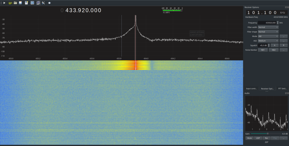
In the upper section of the Gqrx software interface, the frequency spectrum is prominently displayed. Frequencies are plotted along the x-axis, while the y-axis measures the signal strength in decibels, with values closer to zero indicating stronger signals. For a detailed analysis, setting a specific target frequency is crucial. I have selected 433.920 MHz, as this is the frequency used by the remote control, a point discussed in part 1 of the article.
The spectrum analysis verifies that the remote control operates on this frequency, with the strongest signal at 433.924 MHz. Fluctuations are noted within the range from 433.919 MHz to 433.945 MHz. The presence of a single peak simplifies the analysis by ruling out modulation types like GFSK and FSK.
Below the spectrum, another graph shows activity at this specific frequency. A white line indicates intense activity at our spectral peak. The horizontal blue lines, which represent “breaks in the signal,” are typical of amplitude modulation (AM), in this case, OOK. Adjusting the left panel to AM mode produces an audio output resembling Morse code, further confirming the use of OOK modulation. This setup provides a clear indication of how the signal modulates, facilitating a more refined and accurate analysis.
Note : I adjusted the Squelch parameter to -45 dB, as there is significant electromagnetic noise around -50 dB. Setting the squelch to this level helps to filter out this background noise, resulting in a cleaner and more interference-free signal.
With the ‘rec’ button located at the bottom right of the interface, the demodulated signal can be recorded in WAV (audio) format. This feature enables the capture of channel activity for later analysis of the signal, as discussed in the following chapter.
Signal analyse with Audacity
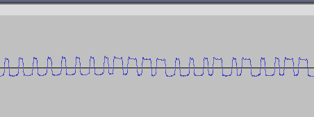
Upon examining the Wav file mentioned earlier using an audio tool like Audacity, the demodulated signal sent by the remote control is clearly visible. It’s apparent that the signal is transmitted repeatedly, a common practice in radio communications to ensure reliability. This redundancy is crucial because radio messages can easily be interfered with or disrupted. Here is what the visual representation of our signal looks like:

When you zoom in on one of the signal blocks, the data being transmitted becomes clearly visible. This data can be analyzed either visually or through software, as will be discussed in the next chapter. Capturing a clean signal involves several steps: adjusting for noise, selecting the correct modulation type, choosing the appropriate antenna, and fine-tuning its placement. An essential piece of data to gather during this phase is the baud rate of the signal. Knowing this will aid in later stages when working with a transmitter/receiver like the Yardstick.

Analyse signal with ooktools
To improve signal reading and configuration (such as baud rate), I use the ooktools utility. This tool is specifically designed for reading OOK modulation data. It’s installed within the same virtual environment as rfcat because it relies on the rflib library to operate. The setup process is straightforward and user-friendly. Here are the commands for both installation and usage:
$ git clone https://github.com/leonjza/ooktools.git
$ python setup.py install
$ ooktools --help
         _   _           _
 ___ ___| |_| |_ ___ ___| |___
| . | . | '_|  _| . | . | |_ -|
|___|___|_,_|_| |___|___|_|___| v1.4
On-off keying tools for your SD-arrrR
https://github.com/leonjza/ooktools

Usage: ooktools [OPTIONS] COMMAND [ARGS]...

Options:
  --help  Show this message and exit.

Commands:
  gnuradio  GNU Radio Commands.
  signal    Signal Commands.
  wave      Wave File Commands.
Using ooktools is quite straightforward, though it’s important to note that it doesn’t work in every scenario; it requires a clean signal to function effectively. Nonetheless, it proves to be very useful when the conditions are right. Here’s a guide on how to use it:
$ ooktools wave binary --source ./signal.wav

         _   _           _
 ___ ___| |_| |_ ___ ___| |___
| . | . | '_|  _| . | . | |_ -|
|___|___|_,_|_| |___|___|_|___| v1.4
On-off keying tools for your SD-arrrR
https://github.com/leonjza/ooktools

Total Samples: 3652, Min: -5477, Max: 11029, Mean: 2776.0
Cleaning up 3652 data points...
Samples in (Shortest Peak: 16) (Longest Peak: 115)
Math for baud rate will be 1.0/(16/float(48000))
Source wave file has baud rate of: 3000
Skipping for 115 as it fits 7 times(s)
[ ] indicates number of breaks.
Key Data:  [7] 001xxxxxxxxxxxxxxxxxxxxxxxxxxxxxxx111100001110101100
Here are the keys I managed to extract:
001xxxxxxxxxxxxxxxxxxxxxxxxxxxxxxx110001110101111111
001xxxxxxxxxxxxxxxxxxxxxxxxxxxxxxx110001110101111111
001xxxxxxxxxxxxxxxxxxxxxxxxxxxxxxx110000000011001111
001xxxxxxxxxxxxxxxxxxxxxxxxxxxxxxx110000000011001111
001xxxxxxxxxxxxxxxxxxxxxxxxxxxxxxx110000000011001111
001xxxxxxxxxxxxxxxxxxxxxxxxxxxxxxx110000000011001111
001xxxxxxxxxxxxxxxxxxxxxxxxxxxxxxx110000000011001111
001xxxxxxxxxxxxxxxxxxxxxxxxxxxxxxx110000000011001111
001xxxxxxxxxxxxxxxxxxxxxxxxxxxxxxx111100001110101100
To my surprise, the system implements a rolling code mechanism. Considering the relatively low cost of this model, I initially expected it to emit the same key, particularly given the logistical challenges associated with managing multiple remotes and devices. The data collected so far provides some insights into how the rolling code operates, although these insights aren’t conclusively certain. I have been cautious about gathering further data to avoid damaging the garage door mechanics or causing the remote and garage system to become desynchronized. Currently, I have access to just one key. Based on the information at hand, here are my assumptions about the system:
- The transmitted key includes a fixed part and a rolling code section.
- The fixed portion consists of a combination of 36 bits and 16 bits.
- Each key features a distinct fixed part.
- The fixed part is composed of a preamble value and a remote ID.
Conclusion
We successfully intercepted the radio communication between a garage door and its remote control. While the process isn’t overly complex, it does necessitate a certain amount of equipment and a significant time investment to develop expertise in radio technologies, such as modulation and Software Defined Radio (SDR). Furthermore, hardware hacking can become quite costly. You frequently require various pieces of equipment and often find yourself lacking the necessary tools. Despite these challenges, the effort is rewarding and engaging.
Following this experiment, there are several intriguing possibilities to consider for future exploration: accurately reading the signal using rfcat and the yardstick, developing a tool to brute force the rolling code portion, and reverse engineering the rolling code. These could potentially be topics for a new blog post.